Outlines on the surface
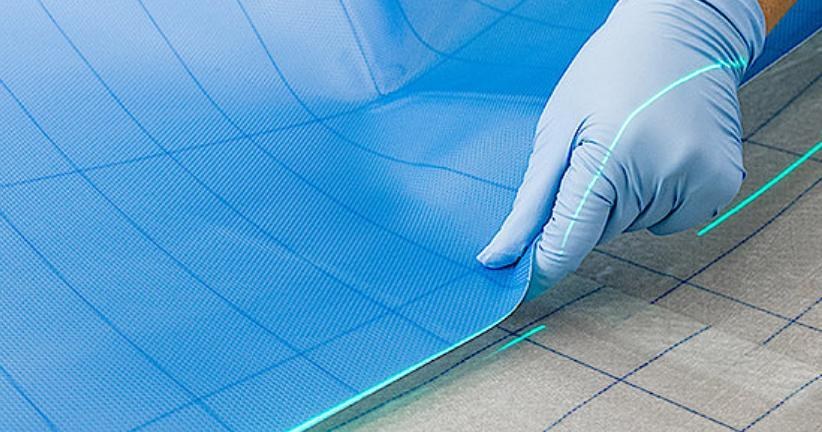
Design data drives projection tasks. Outlines displayed on the mold provide a reference for the manual positioning and placement of glass-fiber fabric.
 LASER PROJECTION
3D LASER PROJECTION
3D Laser-Assisted Layup
Project layup outlines onto curved mold surfaces. Connect design data with manual placement on the wind blade production floor.
DESIGN TO SURFACE
Bring layup information to the point of work. Visual outlines help operators identify where to position material and align its edges.
Design data drives projection tasks. Outlines displayed on the mold provide a reference for the manual positioning and placement of glass-fiber fabric.
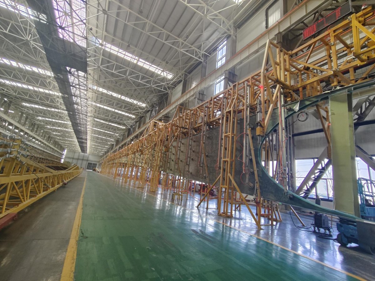
Manage projection tasks by work group at the blade root, mid-span and tip, with clearly defined areas along a long blade.
Central task management combines with tablet and wrist-mounted controls so operators can manage tasks from their working position.
CONNECTED AT THE POINT OF WORK
A central controller organizes projection tasks. Projectors and work groups are configured for the site layout, with tablet and wrist-mounted controls for operators.
THE LAYUP WORKFLOW
Define the application around your blade design, mold and layup process, from data preparation to operation on the floor.
Review layup outlines and process information to define the inputs needed for projection tasks.
Establish the relationship between projection coordinates and the work surface for the mold and equipment layout.
Organize tasks by areas such as root, mid-span and tip, then display the current layup outline.
Operators position and place material along the outlines, advancing tasks according to the layup process.
WIND BLADE MANUFACTURING
From an individual work position to grouped operations, discuss a projection-assisted approach around your blade geometry, dimensions and working practices.
View the layup animation ↗Animation illustrates the application concept.APPLICATION NOTES
The system provides visual guidance for manual layup. Operators place and compact material according to the process requirements.
Blade and mold dimensions, layup design data, workstation layouts, installation conditions and your current operating process support the application assessment.
Projection coverage, mold geometry, installation distance, obstructions and work-group requirements are assessed to define the project configuration.
Accuracy, calibration time and cycle time need to be agreed against site conditions, design inputs and an acceptance method. Contact the team to discuss your operating conditions and validation requirements.
LET'S TALK ABOUT YOUR APPLICATION
Tell us about your mold, workstations and layup requirements. We will help define the application.
Contact the solutions team ↗Hunan Nuoyi Technology Co., Ltd.
No. 776 Mingyue Road, Tianyuan District, Zhuzhou, Hunan, China